Search...

In power supply design, bypass and decoupling capacitors are essential for filtering out voltage noise and ensuring stable operation. But with so many values and package types available, many engineers ask:
“Should I choose one large capacitor or combine several?”
“What value of capacitor will effectively suppress high-frequency noise?”
“What is the self-resonant frequency (Fsr), and why does it matter?”
Let’s break it down simply — and practically.
Ideally, a capacitor's impedance decreases as frequency increases, following the formula:
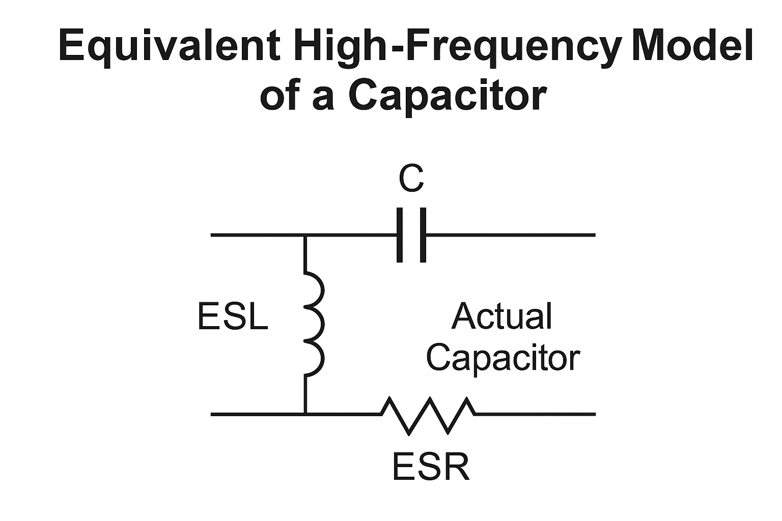
But in the real world, every capacitor includes parasitic inductance (ESL) and resistance (ESR), forming an LC series resonant circuit.
At its self-resonant frequency (Fsr), the capacitor exhibits lowest impedance.
Below Fsr, it behaves like a capacitor.
Above Fsr, it becomes inductive and loses its filtering ability.
This means a capacitor is only effective up to its Fsr.
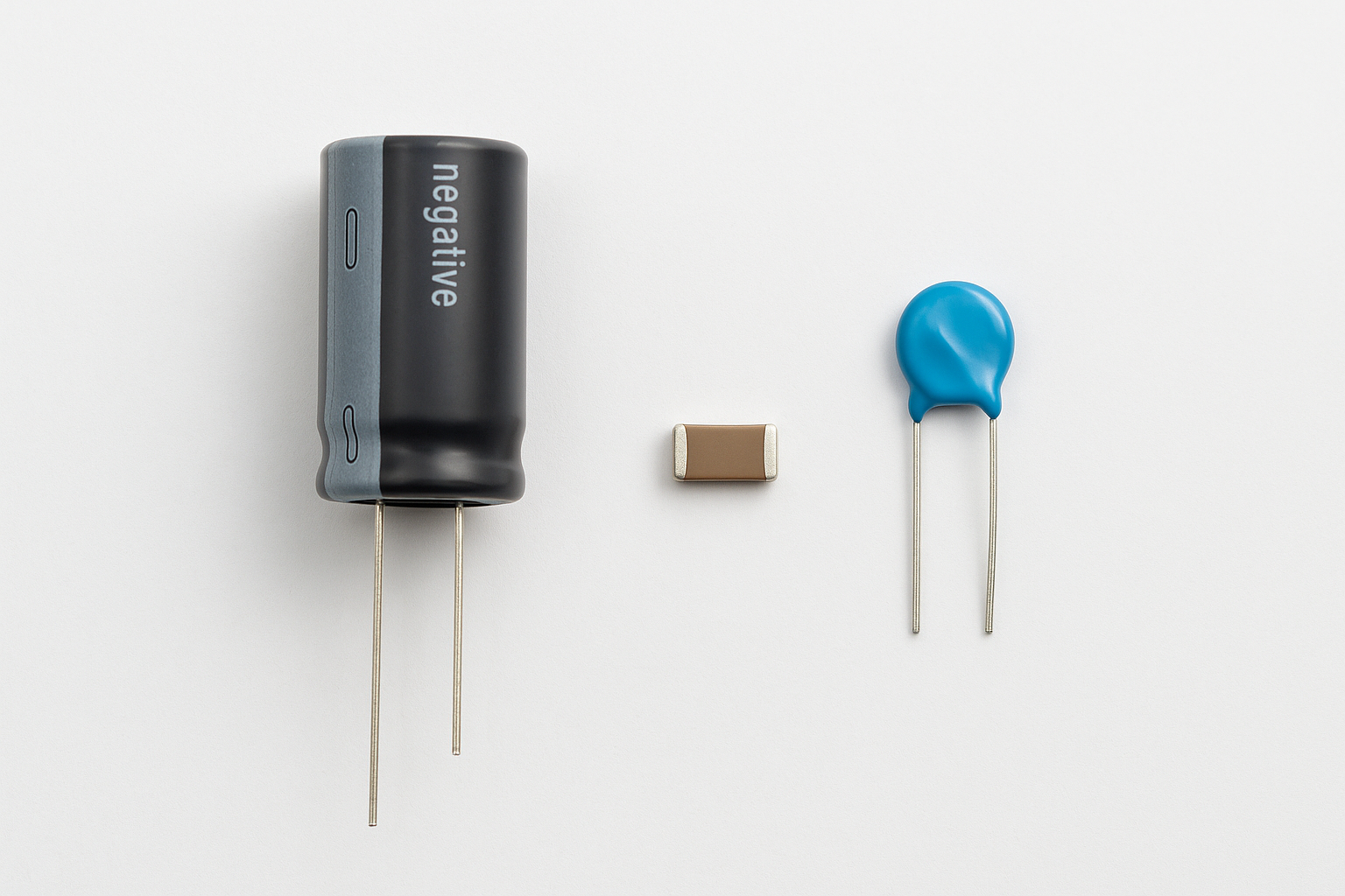
Large capacitors like 10μF are great at filtering low-frequency ripple, but they typically have low Fsr (a few MHz). For high-frequency transients, they’re practically useless.
On the other hand, small capacitors — like 100nF or 100pF in 0402 or 0603 packages — have higher Fsr (100–500 MHz), making them excellent for high-frequency noise suppression.
Combining capacitors with different values — say 10μF + 0.1μF + 100pF — helps cover a wide frequency range. The general rule of thumb: use values at least two decades apart.
You can find Fsr values in the capacitor’s datasheet. For example:
100pF 0402 ceramic: Fsr ≈ 500 MHz
0.1μF 0603 ceramic: Fsr ≈ 100 MHz
10μF 0805 ceramic: Fsr ≈ 5–10 MHz
Electrolytic 10μF (DIP): Fsr may be < 1 MHz
Smaller packages = higher Fsr due to lower parasitic inductance.
Bypass capacitors should always be placed as close as possible to the power and ground pins of ICs. This reduces trace inductance and ensures effective high-frequency suppression. Remember, long traces = unwanted inductors!
| Purpose | Capacitor Type | Value | Notes |
| Low-frequency filtering | Electrolytic | 10μF–100μF | Bulk filtering |
| Mid-frequency noise | Ceramic X7R | 0.1μF–1μF | Typical for decoupling |
| High-frequency spikes | Ceramic NP0/C0G | 100pF | Handles MHz-range noise |
Engineer's Insight
“In practice, one capacitor is rarely enough. A smart combination — backed by understanding of Fsr — can make or break your power design.”
Choosing the right filter capacitors isn’t just about value — it’s about behavior across frequency. By understanding Fsr, ESL, and combining capacitors of different sizes, you can ensure stable, noise-free power delivery across your entire design.
Need help with component selection or PCB layout advice? Contact our engineering team — we're happy to assist.
 More information?
AXTEK Series NYQUEST CMSEMICON ST MICROELECTRONICS Featured Manufacturers Puya MCUs ICMAN Touch Chips ZXInfoTek Holtek MCUs MORNSUN Modules
Company Profile Certificates Terms & Conditions Privacy Statement


 MCU Solutions
 PCBA Solutions
 Bluetooth Solutions
 FAQ
FAQ Contact Us
 Company News
 Technology News
 Industry News
 PCBA News
 Company Profile
 Certificates
 Terms & Conditions
 Privacy Statement
 Home Appliances
 Beauty Appliances
 Lighting
 Kid's Toys
 Security Alarm
 Health Care