Search...



GENERAL DESCRIPTION:
MX25L51245G is 512Mb bits Serial NOR Flash memory, which is configured as 67,108,864 x 8 internally. When it isin two or four I/O mode, the structure becomes 268,435,456 bits x 2 or 134,217,728 bits x 4. MX25L51245G featurea serial peripheral interface and software protocol allowing operation on a simple 3-wire bus while it is in single I/Omode. The three bus signals are a clock input (SCLK), a serial data input (SI), and a serial data output (SO). Serialaccess to the device is enabled by CS# input.When it is in two I/O read mode, the SI pin and SO pin become SIO0 pin and SIO1 pin for address/dummy bitsinput and data output. When it is in four I/O read mode, the SI pin, SO pin, WP# and RESET# pin (of the 8-pinpackage) or and NC pin become SIO0 pin, SIO1 pin, SIO2 pin and SIO3 pin for address/dummy bits input and dataoutput.The MX25L51245G MXSMIO (Serial Multi I/O) provides sequential read operation on the whole chip.After program/erase command is issued, auto program/erase algorithms which program/erase and verify thespecified page or sector/block locations will be executed. Program command is executed on byte basis, or page (256bytes) basis, or word basis for erase command is executed on 4K-byte sector, 32K-byte block, or 64K-byte block,or whole chip basis.To provide user with ease of interface, a status register is included to indicate the status of the chip. The status readcommand can be issued to detect completion status of a program or erase operation via WIP bit.Advanced security features enhance the protection and security functions, please refer to the security featuressection for more details.When the device is not in operation and CS# is high, it will remain in standby mode.The MX25L51245G utilizes Macronix's proprietary memory cell, which reliably stores memory contents even after100,000 program and erase cycles.
FEATURES:
GENERAL
• Supports Serial Peripheral Interface -- Mode 0 andMode 3
• Single Power Supply Operation
- 2.7 to 3.6 volts for read, erase, and program operations
• 536,870,912 x 1 bit structure or 268,435,456 x 2 bits (two I/O mode) structure or 134,217,728 x 4 bits (four I/O mode) structure
• Protocol Support - Single I/O, Dual I/O and Quad I/O
• Latch-up protected to 100mA from -1V to Vcc +1V
• Fast read for SPI mode
- Supports clock frequencies up to 166MHz for allprotocols
- Supports Fast Read, 2READ, DREAD, 4READ,QREAD instructions
- Supports DTR (Double Transfer Rate) Mode
- Configurable dummy cycle number for fast readoperation
• Supports Performance Enhance Mode - XIP(execute-in-place)
• Quad Peripheral Interface (QPI) available
• Equal 4K byte sectors, or Equal Blocks with 32Kbytes or 64K bytes each
- Any Block can be erased individually
• Programming :
- 256byte page buffer- Quad Input/Output page program(4PP) to enhanceprogram performance
• Typical 100,000 erase/program cycles
• 20 years data retention
SOFTWARE FEATURES
• Input Data Format
- 1-byte Command code
• Advanced Security Features
- Block lock protectionThe BP0-BP3 and T/B status bits define the sizeof the area to be protected against program anderase instructions
- Advanced sector protection function (Solid andPassword Protect)
• Additional 4K bit security OTP
- Features unique identifier
- Factory locked identifiable, and customer lock- able
• Command Reset
• Program/Erase Suspend and Resume operation
• Electronic Identification
- JEDEC 1-byte manufacturer ID and 2-byte de- vice ID
- RES command for 1-byte Device ID- REMS command for 1-byte manufacturer ID and1-byte device ID
• Supports Serial Flash Discoverable Parameters(SFDP) modeHARDWARE FEATURES
• SCLK Input - Serial clock input
• SI/SIO0 - Serial Data Input or Serial Data Input/Output for2 x I/O read mode and 4 x I/O read mode• SO/SIO1 - Serial Data Output or Serial Data Input/Outputfor 2 x I/O read mode and 4 x I/O read mode
• WP#/SIO2 - Hardware write protection or serial data Input/Output for 4 x I/O read mode
• RESET#/SIO3 - Hardware Reset pin or Serial input & Output for4 x I/O read mode
• NC/SIO3 - No connection or Serial Data Input/Output for 4 xI/O read mode
• RESET# - Hardware Reset pin
• PACKAGE
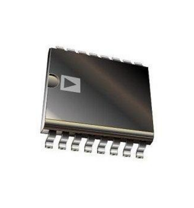
- 16-pin SOP (300mil)
- 8-land WSON (8x6mm)
- 24-Ball BGA (5x5 ball array)
- All devices are RoHS Compliant and Halogen-free
You can get your MXIC MX25L51245GZ2I-08G STOCK solution by flling out the form below and we will contact you immediately.
AXTEK Series NYQUEST CMSEMICON ST MICROELECTRONICS Featured Manufacturers Puya MCUs ICMAN Touch Chips ZXInfoTek Holtek MCUs MORNSUN Modules
Company Profile Certificates Terms & Conditions Privacy Statement


 MCU Solutions
 PCBA Solutions
 Bluetooth Solutions
 FAQ
FAQ Contact Us
 Company News
 Technology News
 Industry News
 PCBA News
 Company Profile
 Certificates
 Terms & Conditions
 Privacy Statement
 Home Appliances
 Beauty Appliances
 Lighting
 Kid's Toys
 Security Alarm
 Health Care